Description
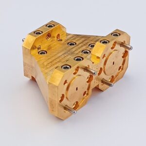
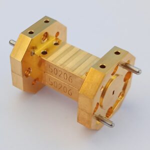
Our 90° waveguide bends have an arm lenght of 1″ each side and are available between 50 GHz and 1700 GHz. They are all manufactured using split block technology, which makes them highly precise, very robust and protected against bending and twisting. Due to this manufacturing technique and the goldplating of all surfaces, they offer minimal insertion losses and an excellent VSWR. The waveguides are equipped with UG387/U-M flanges on both sides as a standard, special requests can be taken into account at any time.
Key Features
- Frequency: 50 GHz to 1700 GHz
- robust and elegant design
- manufactued in splitblock technology
- low insertion loss
- excellent VSWR
- available E- as well as H-Plane Bend
- long version, screwable from the back
Applications
- high precision measurement applications
- measurement and instrumentation
- VNA measurements
Specifications
| Band Designation | Frequency [GHz] | S21 typ. [dB] | S11 typ. [dB] | Partnumber E-Plane |
Partnumber H-Plane |
|---|---|---|---|---|---|
| WR 15 | 50-75 | 0,26 | <-40 | 1551 | 1499 |
| WR 12 | 60-90 | 0,26 | <-40 | 1552 | 1500 |
| WR 10 | 75-110 | 0,3 | <-40 | 1553 | 1501 |
| WR 8 | 90-140 | 0,5 | <-40 | 1554 | 1502 |
| WR 6.5 | 110-170 | 0,76 | <-35 | 1555 | 1503 |
| WR 5.1 | 140-220 | 1,1 | <-35 | 1556 | 1504 |
| WR 3.4 | 220-330 | 1,5 | <-35 | 1557 | 1505 |
| WR 2.2 | 330-500 | 2,4 | <-35 | 1558 | 1506 |
| WR 1.5 | 500-750 | 3,6 | <-30 | 1559 | 1507 |
| WR 1 | 750-1100 | 6 | <-30 | 1560 | 1508 |
| WR 0.65 | 1100-1700 | 9 | <-25 | 1561 | 1509 |
Diagram

In addition to our standard products, each component can be customized to meet your specific requirements.
We are happy to implement index dowel pins as well as modified flanges on request.


